 spectrum for FM radio, DAB radio and TV.")
The subjects on this page are listed in the following order :
Basic Aerial Facts (“Set Top” Aerials, Aerial Positioning / RF Dead Spots & Signal Meters)
Basic Aerial Theory : Yagi type (including definition of aerial “gain” )
Yagis, Double Yagis, Tri Booms and X Beams
Aerial Groups/Widebands (including Wideband V Grouped Gain Graph)
How Do I Know If My Aerial Is A Wideband ?
Signal Strength : “Am I in a strong signal area ?”
"High Gain Aerials” (includes Phased Array & Co-
Types of Aerial (Quality, Size and Group)
ATV`s choice of aerials (sales and installations) (and why we chose them)
Above is a 13 element (see element count) TV aerial [above left] and 3 element DAB aerial [above right], illustrating the main components found on Yagi type aerials.
Note the use of a cradle on the TV aerial which it is good practice to use for all “high gain” aerials (particularly X Beams) due to their higher wind loading. Mounting cradles strengthen the aerial and reduce the twisting forces exerted on the pole and clamp(s). End mounting aerials can exert
a very high torque and this was exceptionally annoying when we were undertaking aerial tests whilst there was wind about ! On a related point if any aerial is fitted with a cradle this should always be fitted perpendicularly to the dipole so as not to interfere with the tuning of the directors. Similarly the pole can also interfere with the aerial`s tuning as with this DAB antenna.
Incidentally the directors may all look the same size but in a correctly “tuned” antenna they vary, for example the Yagi18A directors come in five different sizes, from 19.8mm at the front up to 22.2mm at the back with a 24.6mm (OD) dipole. At the other end of the TV frequency band the wavelengths are that much shorter, and therefore the dimensions of the elements for a Yagi18C/D are 14.0mm, 16.0mm and 16.3mm respectively, see picture of aerial front elements.
As more elements are added to a Yagi aerial (provided they are “tuned” correctly) the acceptance angle narrows and the amount of signal “collected” [the ”gain” ] increases. Gain is measured in decibels or dB (this is a logarithmic scale) and for aerials it should be measured as dBd, which
is the increase in signal received from an antenna compared to that which would be measured
from just the dipole on its own. Note that 0dBd does not mean that zero signal would be received
by the aerial, it just means that the aerial only picks up the same amount of signal as the dipole
would on its own, i.e. with no reflector or any directors. In fact the vast majority of FM and DAB
aerials are just dipoles which only have a gain of 0dBd, yet they work fine in most cases.
On the other hand a TV aerial of only 0dBd would need a very strong signal to work OK.
Always remember that there is more than one way to measure gain, e.g. dBi and dBd, the latter
being the more honest parameter. To convert dBi to dBd deduct 2.15 from the dBi figure.
Gain is not everything but it is the simplest most objective measure of the efficiency of the aerial.
Incidentally, always be careful when comparing the quoted gains of aerials.
For any aerial the tuning of the elements is critical. This is a highly specialised job and it is fundamental to the performance of the antenna. If a Yagi aerial is deigned to work over a large section of the band (a “Wideband”) it cannot be tuned precisely and therefore its gain and directivity will be lower. You have to remember that Yagis were originally designed as single frequency aerials. Thus if you really need a high gain aerial and are able to use a grouped antenna on your transmitter, a grouped aerial is always preferable. This is particularly true in the case of A group transmitters, but also (to a lesser extent) K group and B group transmitters. Having said that, most people don`t need a high gain aerial and a Log would be preferable.


Ever since Dr Yagi patented his eponymous aerial
in 1926 people have been trying to improve and adapt it. At the present time there are four main versions, the “conventional” Yagi, the “Double” Yagi, the “Tri Boom” Yagi and the “X Beam” Yagi.
All these use the tuned director / dipole / reflector (see above) to produce gain. Basically the Double Yagi (DY), the Tri Boom and the X Beam (XB) are all attempting to increase the number of directors (and therefore the gain) without making the aerial too long. The Double Yagi places two sets of directors side by side whereas the Tri Boom stacks three sets one above the other.
The X Beam is a variation on the Double Yagi
using either one V shaped director or two shorter directors to mimic the longer flat directors of the Double Yagi and it is an attempt to limit the width
of the aerial, and make it cheaper to manufacture.
.")
.")
")

“Conventional” element count = 18 “Conventional” element count = 30 ?
“Conventional” element count = 57 ? “Conventional” element count = 22 ?
Now we come to the contentious area of “element count”. It was always the convention that each
director was counted as an element, the dipole was counted as one element and the reflector
(in its entirety) was counted as one element. Unfortunately in this marketing dominated world of
ours this simple concept has been eroded. Many manufacturers now count all the individual elements of the reflector as separate elements, and when it come to X Beams some even count each “X” as four elements, when arguably that is double the real figure ! Finally remember that aerial gain is also dependent on the length of the antenna, not just how many elements it has.
The moral of the story is to be very wary of manufacturer`s “element counts”.......
I am not an expert on aerial design, I just test them and know what works. In my experience, for a given number of elements, the highest peak gain figures are achieved by the conventional Yagi.
The next highest efficiency is the Double Yagi, followed by the X Beam and in last place is the
Tri Boom. The best theory I have heard to explain these “league positions” is that since RF
is longitudinal in waveform, the closer the director chain is to the direct line of sight to the
transmitter (along which the wave is propagating) the more efficiently it will work. I must stress here that we are talking for aerials of the same number of elements, obviously a Double, Triple
or X Beam would normally have more elements and may therefore have more absolute gain.
Remember that when talking about aerial gain one must bear in mind that peak gain and
average gain are not the same thing. I have found that Double Yagis and X Beams do seem to “broaden” the gain curve over the conventional Yagis, and the A group and B group gain curves show this quite clearly. This wider gain curve is obviously useful for wideband applications,
which is why we recommend the DY14WB / XB22WB but not the Yagi18 in a wideband version, whereas we do recommend the grouped versions of the Yagi18.
So why do we see so many X Beams and Tri Booms around (most of which aren`t even needed,
see Log Periodic aerials) whilst conventional Yagis are becoming less common and Double
Yagis are strictly for the cognoscenti ? There may be a lot of Tri Booms about, but just because
a particular product is common it doesn`t necessarily mean it`s any good, "stick on your windscreen" car mirrors for instance. Who came up with that crap idea ?
Well some cynics say that X beams and (particularly) Tri Booms look more impressive and so
that`s why people use them, especially aerial installers who can then charge more for them !
Aerials as fashion victims ? Me a cynic ? Not in this world.......
Note, in this article a channel number (CH) refers to a frequency not a programme.
The TV UHF broadcast band in this country stretches from 471 MHz (= CH21 which has a
wavelength of 64cm) at the bottom, to 847 MHz (= CH68 with a wavelength of 35cm) at the top.
Anyone who knows anything about RF (Radio Frequency) will tell you that it is asking a great deal
of an aerial to perform well across such a wide frequency band but certain people have a vested
interest in trying to ignore scientific fact.... The poorer performance of widebands is clearly shown
on the graph showing Grouped v Wideband aerial gain curves. To get around this, when UHF TV
transmissions were introduced in the mid 60s, great care was taken to minimise reception
problems by utilising grouped transmitters and receiving aerials. That is to say all the the
broadcasts from any particular transmitter were fitted into one group of frequencies, stretching
across about one third of the full band. For example Crystal Palace was (and still is ! ) an A group.
The groups were (and still are ! ) as shown in the table below. Note that the groups have
changed slightly over the years, these apparently minor changes can sometimes be significant.
Graph of typical gain curves for “high gain” Yagi 18 element aerials
Notice the lower gain of the wideband antenna over the grouped aerials, and that this is particularly marked at
the bottom of the band,
i.e. group A. It should be
noted that group A was
extended up to CH37
(from CH34) in 1995.
The E group is a
“semi wideband” aerial which sacrifices a bit of
gain at the bottom so
as to increase it at
the middle / top end.
Note some Contract aerials can be very unpredictable in their gain curves, particularly out of their designed for bands.
Also see :
For those who live in areas capable of reception from multiple transmitters the fact that a
wideband can pick up right across the TV spectrum can, ironically, be a negative. This is partly
because it gives more chance of co-
Freeview STBs scan for channels. If they find more than one of a particular MUX they will often put
the first one they come across (which may not be the strongest) in the main selection position,
whilst frequently leaving a more robust channel further up the menu or possibly ignoring it
altogether. If you live in a strong reception area and some of your digital is fine, but some is not,
it is always worth checking for this problem and most STBs can tell you which transmitter they`re
picking up a particular channel from. This multi transmitter reception problem may well get
worse after DSO, when the digital transmitting power will increase considerably, and Digital UK reckon up to 92% of homes will suffer from this “overlap”.
A good example of TX overlap is Sheffield where Emley Moor (a B group and the preferred transmitter) is NNW and Bilsdale (mainly an A group) is NNE. Particularly if the customer has a wideband aerial, when the STB scans it will often find the weaker Bilsdale MUXES first and
ignore, or relegate, the stronger Emley Moor output. If it relegates them, see if it`s put them up in the 800s, e.g. BBC1 on 801, if so can you swap the channels around ?
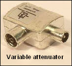
The simplest way round all this is to use an attenuator (only whilst the box is scanning ? ) to tip the unwanted weaker transmissions down the cliff edge whilst leaving the required ones at the top or, if you have the option, try and scan your box manually. Alternatively, if your transmitter is grouped, use of a grouped aerial (or using a diplexer as a filter) may help alleviate the problem.
The roll off in an aerials sensitivity is far greater above the aerials designed for group
than below it, and our own aerial tests confirm this, see gain curves. For example a decent B group aerial will work reasonably well right down the A band. But its response above the B group will only be significant up to about CH55 to 57, see aerial test results, Group Responses. These figures will obviously vary according to the particular aerial and the signal strength in the area.
Note that some cheap crappy Contract aerials can be inconsistent in their gain curves.
Also see local Transmitter Channel Allocations, Digital Nationwide and Digital MUXs.
Finally there is the WIDEBAND aerial which works (to a greater or lesser extent....) across the whole band. Anyone aligned on a transmitter which has changed group (and most have not changed group, see Digital Transmitters) may not receive all of the digital services [or possibly analogue C5] without having their aerial changed. I have deliberately avoided using the term “aerial upgraded" because this implies there was something inferior about their old antenna which is not necessarily the case. I have seen installers replace an A group TC antenna with a wideband Contract aerial, and that`s never been an “upgrade”.
As mentioned above, no Yagi aerial will work efficiently across the whole band. In the RF game (as in life generally ! ) you never get anything for nothing. At all points across the band the gain of
a wideband is inferior to a grouped antenna (of the same model) but the fall off is greatest at the bottom of the band, i.e. group A. In fact such is the widebands inferiority that there is no such thing as a “High Gain” wideband aerial for the A group frequencies, or if there is I`ve yet to come across it. In fact I would say that even the average Contract 10A would be on a par with any wideband antenna..... The only way to get a genuine high gain wideband aerial is to diplex an A group with an E group, or even an A group with a wideband if you`ve already got one of those, although very few people would actually need to do this. Incidentally we have noticed that when extra directors are added to wideband aerials (to make them “high gain” ) the gain increase
tends to be more at the top end than the bottom end and the gain curves for the DAT45 and
DAT75 reflect this as well. To put it into laymans terms a wideband aerial is the equivalent of “a jack of all trades but master of none”, see aerial groups, widebands, minibuses & vasectomies.
That said, if you`re in a reasonable signal area a wideband will work fine, and in fact we actually recommend Log Periodics (which are widebands) in good or medium areas.
OK, I admit it, apart from Log Periodics I don`t like widebands because they offend my
perfectionist sensibilities, although I must say I`m pretty impressed by the DY14WB.
The latter aerial has exceptional performance for its size.
The fact that one of the dipoles can be resonant for any part of the broadcast band means that
Log Periodics have a pretty flat signal gain curve. They also have a tight polar response (i.e. they
are less likely to pick up signals you don`t want), a decent “cross polar rejection” and low wind
loading. Finally Logs have good suppression of impulse noise which can be a cause of intermittent blocking and freezing on digital signals. Manufacturers have been known to claim
that Log Periodics short this noise out to earth, but it`s just as likely that the aerials` tight polar response just means they`re less likely to pick it up in the first place !
Unfortunately Logs have a relatively low gain figure and the they`re only available in wideband. Thus they are only really suitable for areas with a fairly good signal, though the Log 40 is OK for medium signal strength areas as well. Apart from this Achilles heel the Log is one of the best antennas, particularly for digital, which is why we use them wherever possible, as do the broadcast authorities, for both receiving and transmitting.
All of which begs the question, why don`t you see more Logs around ?
Well I think there are three main reasons.
First, the Log Periodic is a fairly recent development, more will appear as time passes.
Second, most aerial installers are notoriously tight, logs are more expensive than the
equivalent small Yagi and they`re twice the price of a Contract aerial.....
Third, many installers are stuck in their ways and use what they`ve always used, especially if it`s
cheaper as well ! See ATV`s choice of aerials and TV aerial tests.
VHF (FM & DAB) and
UHF (TV) frequencies.
This is what we`re
trying to receive
through the aerial !
I`m an aerial man and
I don`t particularly like
satellites, but just out
of interest the signals
received at the dish
(from a satellite) are of the order of 10 GHz,
and the signal sent from the LNB to the receiver
box is 1 to 2 GHz.
Log periodic aerials use the same basic
mechanism (of director + dipole + reflector) as a
Yagi but instead of having one dipole (onto which
all the RF is “focused” ) they use all the elements
as potential dipoles. I say potential because for
any particular frequency only one of them will be
“resonant”, i.e. producing significant signal down
the cable. At this particular frequency the element
in front will act as a director and the one behind
as a reflector.

If one looks closely at the various grouped aerials one can see that the elements become
smaller as the frequency rises and the wavelength shortens. The clearest example of this are
amateur radio antenna arrays. Thus it can be appreciated how an aerials gain is not just down
to the number of elements or its length. The most important factor is the “tuning” of the elements.
This is why an A group aerial (no matter how high its gain) will not receive the “out of band”
frequencies. Furthermore, the higher up the band they are, the lower its response to them will be.
Note how the element for the A
group is the longest because it
is designed to be resonant with
the lowest frequencies, which
have the longest wavelengths.
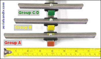
The coloured “bungs” in the
ends of the booms will be
noted, they are to denote the
group of the aerial. If an aerial has a coloured bung it is a
grouped type. The vast majority of aerials with a black bung are widebands, but not all of them.
Also see how to identify a
gain grouped aerial, or a really high gain wideband aerial if your transmitter is a wideband.
If you use anything smaller the nett advantage (over a Log 40) is debatable.

The aerial and its downlead (see Cable) are taken for granted by almost everyone, but they are
just as important as the TV and in fact (electronically speaking) are actually part of it. Many
people will happily spend hundreds of pounds on their television but many are unwilling to
spend any more than is absolutely necessary on their aerial installation. This is an important
point because the difference in gain between a cheap "contract" aerial and, say, a Yagi18 of the
same group, can sometimes be quite small, and will not usually transform a really poor picture
into a perfect one. But it will make some difference, and that difference (particularly with Digital
signals, see “Digital cliff edge") could make all the difference. On the other hand there are
big differences in build quality between many of the aerials available on the market.
Remember that a decent aerial installation should last 20 to 30 years or more *, and at the end
of the day what`s the cost of a good quality aerial install compared to the cost of the average TV,
or your sanity when your Digital picture keeps freezing ? ! ?
* With the possible exception of the cable, particularly if running over a roof.
1 We do not normally recommend fitting TV aerials in lofts, although they can work OK in
strong signal areas. That said, after Digital Switchover Over when the power is to be increased
many more people may well find a loft aerial is sufficient. Even more problematic than a loft aerial
is a “Set Top” aerial and if you get perfect digital off one you`re lucky indeed and you must live
in a very strong signal area. Using a “booster” antenna is also unlikely to give you a perfect
picture for the reasons given in the amplifiers page. I`d recommend a feed from your outside
aerial if one of the standard type “set top aerials” doesn`t work, though one of the latter should
outperform the kind of “loop” antenna that many TVs come supplied with.
An Omnidirectional type aerial is even less likely to be effective, they actually have
negative gain. If you get ever get good results from one you`re probably in an excellent signal
area, a coat hanger would probably work as well ! See Aerials for Boats & Caravans.
2 Aerial positioning can be of critical importance, particularly when anything is close
to the aerial, e.g. the chimney. Bear in mind that at UHF frequencies the wavelengths are
between 14” and 25” so moving an antenna a few feet (vertically or laterally) can sometimes
make a big difference to signal strength or ghosting.
You may have wondered why some aerials are mounted (or polarised) vertically and some horizontally.
To work efficiently aerials must be polarised in the same plane as the transmitter (TX) they are receiving from.
All main TXs such as Emley Moor or Crystal Palace are horizontally polarised whereas repeaters (so called because they receive the signal from a main TX then rebroadcast it) are usually vertically polarised. The reason for this use of vertical and horizontal polarisation is to take advantage of the fall off in response (to a signal of the opposite polarity) to
minimise co-
It should be stressed that CPR can be greatly influenced by nearby objects, e.g. the roof or the chimney, because RF waves can be cross polarised when they`re reflected, even off the ground !
This helps explain why our figures for Cross Polar Rejection are lower than those of the manufacturers, because theirs are obtained in a lab where such cross polarisation does not occur, unlike in the real world..... We once went to a job where the aerial installation had fallen down and was now vertically polarised on Belmont (which is horizontal) but it still worked perfectly because the roof was cross polarising all the received signal ! When we deliberately cross polarised our shop aerial the (analogue) signal went from very good to awful, but if you are in a strong enough signal area even an incorrectly polarised aerial will still work reasonably well, despite losing 90% (or more) of the signal ! Yet again, RF is a black art, it`s not a science......
Vertically polarised aerials will be more susceptible to picking up off beam transmissions
(the main cause of ghosting and co-
from the sides the antenna is effectively a vertical dipole.
Virtually every TV aerial ever manufactured can be polarised horizontally or vertically.
Signal Strength : “Am I in a strong signal area ?”
This is one of the most important articles on this entire website, read it carefully !
Signal strength and signal quality aren`t be the same thing but generally speaking
if you`ve high signal strength at the (unamplified) aerial it`s likely the signal
quality will also be good, excluding co-
The potential range of signal strengths available throughout the country is huge.
Some people live in such a poor area that even a “high gain” grouped XB16 aerial with a mast
head amplifier will still not get them a good picture.
Others, living within sight of a main transmitter, will get a perfect picture with a “set top” aerial or (in some rare cases) just the lead into the tuner, i.e. no aerial at all !
Although a Log40 aerial will work fine in up to 90% of (outside) installs we would usually recommend a different antenna if you live in a poor reception area.

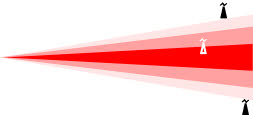
Basically (all other things being equal) the more elements an aerial has, and the longer the
aerial is, the narrower the acceptance angle / polar diagram is and the more gain it will have.
Unfortunately there is an inverse square law over the addition of elements to achieve more gain.
Adding 2 elements to a dipole (to give a 3 element aerial) will give a relatively large increase in
gain, but adding an extra 2 elements to an 18 element aerial will make very little difference.
The law of diminishing returns really starts applying itself in a big way which is why we end up
stocking XB16s, anything smaller wouldn`t give significantly more gain over a Yagi 18.
As mentioned in the section on aerial groups, one of the biggest factors determining an aerials
efficiency/gain (particularly at the bottom of the band) is if it is a grouped antenna or a wideband.
In fact there is no such thing as a “High Gain” wideband aerial for the A or K group frequencies.
Nor a really high gain wideband aerial for the B group frequencies ? I invite you to study the test results for all groups, A group, B group and K group aerials, then make up your own mind.
That said, grouped aerials may have more gain but I`ve never seen the point of 10 element
Don`t forget that aerials never work as well in lofts as they do outside so if you intend to site your antenna inside it may be wise to go for a slightly higher gain type.
From the point where the aerial would be mounted can you see the transmitter ?
If so, and the transmission pattern is not restricted in your direction (the restrictions which we know of are listed on Digital Nationwide and/or the relevant transmitter page) then it`s a fairly
safe bet that you`re in a strong, or very strong, signal area !
It may even be the case that you don`t need a different aerial, you need an attenuator !
Thus, in order to choose the best aerial, it is very helpful to know
the signal strength in your location. For those who do not know the latter, and most people don`t, there are a few pointers one can use to discover this. You could try one of the signal strength prediction websites, but I have to tell you they aren`t very accurate, though to be fair, you wouldn`t really expect them to be.
Remember you can have too much signal, the latter can actually
contribute to interference. That said, it`s usually pretty easy to
add an attenuator to reduce the signal level and that, if used with a
a high gain aerial, also improves your signal to noise ratio.
.")
What is a "High Gain"aerial ?
“High Gain” is obviously a relative term but generally speaking an aerial with 18 elements (or more) is considered to be so. However element count is a bit of
a contentious issue, and I`d take most manufacturers element counts with a large pinch of salt.....
It must be stressed that setting up a phased array can sometimes be difficult / time consuming and there are no guarantees how well it will work either ! That said, they can be very effective against ghosting/multi path because they reduce the beam width and increase the front to back ratio, plus the reflected signals should be received slightly out of phase and therefore reduced.
Note the wavelength at the bottom of the UHF band
is 64cm ( = CH 21) and at the top it is 35cm ( = CH 68).
For more information see Bill Wright`s articles
on Stacking and Eliminating Ghosting.
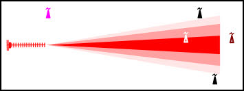
The transmitter on the right is Birchover, a repeater in the Peak District. The bottom pair of aerials are 18 element Yagis in a phased array and are used to receive the signal from Stanton
Moor. The latter is only just visible above the trees thus
dictating the use of a pair of “high gain” Yagi receiving aerials.
Stanton is itself a repeater and receives its signal off Waltham.
The top array uses a couple of Log Periodics to retransmit the
signal into Birchover village.
Contract Aerials
The (top) 18 element version is horizontally polarised whereas the (bottom) 10 element type is polarised vertically
Types of aerial (Also see Yagis, Double Yagis, Tri Booms & X Beams)
There are three main variables in aerial type. Quality, Size and Group.
In Quality terms "Contract" aerials (the type with the plate type rear reflector) are generally at
the bottom of the pile. The elements on a Contract are of thinner/slimmer gauge alloy, in fact they
have about 35% less metal than those on our Yagi18s. The only aerials with a weaker standard
of construction than Contracts are the cheapo X-
because their elements are so thin (e.g many of the Philex, SLX, Labgear or Maxview aerials).
The Contract cradle (if fitted) is smaller and doesn`t have a tilting clamp, the latter allows the aerials elevation to be altered. The latter can sometimes help to maximise signal acceptance and reduce interference, usually by tilting the aerial upwards slightly at the front.
The Contract aerial rear reflector is made of thin alloy plate which as well as being physically
weak, has a relatively high wind loading for its small size.
Most Contract aerials (particularly older ones) do not have a "balun" in the dipole. These are
usually in the form of a small PCB built into the dipole assembly and they are designed to
maximise the signal by impedance matching the dipole to the cable, hence the name from the
term balanced unbalanced. They also said to help eliminate impulse interference which
can be one of the causes of intermittent blocking or pixellation on digital signals. That said, the
best aerials for eliminating impulse interference are Log Periodics, which theoretically short it
out to earth, assuming the aerial is bolted or lashed to the brickwork of the house.
Note that a Log Periodic does not need a balun because they have a natural impedance of
75 Ohms across the full band, due all the individual elements being, in effect, half wave dipoles.
Also see interference tests & screened amps/splitters.
use an attenuator (preferably a variable one) to tip the interfering signal onto the wrong side of
the Cliff Edge while keeping the required one at the top. Another approach is to resite the aerial
(say down the side of your house) and attempt to shield it from the rogue transmitter.
The ultimate form of high gain aerial is the Phased Array though these are not generally
installed just to increase gain. A phased array is two (or more) aerials linked together on to one
down lead. The cables from each of the aerials to the combiner should be exactly the same
length, though this is slightly less important with Log Periodics than with Yagis. The distance between the two antennas should be about one metre. Once the array is in situ experimentation should be undertaken to optimise the signal by varying the distance between the aerials and moving the antennas (front to back) relative to each other. Assuming the aerials are perfectly in phase then in theory it`s possible to obtain 3.5dB extra gain compared to a single aerial (which
is a significant increase) but in practice losses in the combiner [usually a splitter “in reverse”]
will generally reduce this figure to between 1.5 and 2.5dB. It cannot be over emphasised how important it is for the two antennas to be perfectly in phase at the point where the combiner joins them together therefore a decent meter (not a £20 job.....) is essential when setting up a phased array. Any phase difference may very well give less gain and more ghosting, in fact if the two aerials were 180 degrees out of phase it would be theoretically possible to get no signal !
required source more than that from the unwanted one. If the resultant level is too high the attenuator then knocks both signals back down but maintains the increased difference between them. With
Digital signals in particular it is sometimes possible to just
Unfortunately not all X Beam type aerials are created equal. Maybe it`s something to do with the basic design of X Beams (it may be costly to manufacture one which is sufficiently rugged) but
the truth is many of them are rather flimsy to put it mildly. In fact some of these cheapo X Beams really are “Bacofoil” aerials, try bending the elements and you`ll see what we mean.....
We are quite particular about which models of aerial we sell.
Having said all the above virtually all aerials can be strengthened by junking any supplied wing
nuts and fitting conventional nuts instead. These are far stronger and can also be tightened more
effectively, do not over tighten them though ! If “Nylocs” are used (the type with the nylon insert to
prevent them working loose) the fastening should never fail.
To be honest I cannot understand why manufacturers use wing nuts at all, lets face it 99% of
people fitting an aerial would have a spanner anyway and all professional installers have a
decent ratchet spanner, so fitting a conventional nut would actually be easier to tighten up !
Yet another case of manufacturers not talking to their customers ?
Note. Nothing can compensate for an aerial which is manufactured in a flimsy manner
to start off with. The easiest way to find out how well made your antenna really is ?
Try bending the elements, you may be shocked by how flimsy they are..........
Next we come to the Size of the antenna.
Most models of aerial are available in 2 or 3 sizes (e.g. 10 element or 18 element) to suit the
particular installation. An appropriate analogy would be the same model of car being available
with different engine sizes. The number of elements is only a guide to an aerials gain, and these
days “element count” is as much to do with marketing as anything else.
There is no point in fitting an aerial bigger than is actually required, though an installer (or an
aerial supplier) trying to sell the job up may disagree with that !
Too much signal can be detrimental and there would also be an increase in wind loading.
Remember, most people do not need a big “high gain” aerial.
Finally we have the aerials Group.
Historically most ranges of aerial have been available in all the major groups and wideband but
there is now a trend by some manufacturers and suppliers to only deal in widebands. One
reason includes the fact that more transmitters now need a wideband but just as importantly (for
them) is the fact that it`s much easier to manufacture just one aerial group. Even more
significantly it`s far easier to sell just widebands rather than have to go into all the complexities
of which transmitter the customer is on and which group would be a suitable choice etc.
The downside, as we have seen, is that widebands have inferior performance because they are
a design compromise, see TV Aerial Tests.
* I regularly visit Knaresborough and for some reason I cannot fathom there are a few houses in that locality which use this particular antenna on Emley Moor.
Why is that so surprising ? All DAT aerials are widebands and Emley Moor is a B group !
A Yagi18B would work a bit better, look neater, have much less wind loading, and be cheaper as well ! And an XB16B would comfortably outperform a DAT45 or DAT75.
To continue the car analogy having a wideband aerial on a grouped transmitter is the equivalent
of running round in a minibus (rather than a car) when you`ve only got a wife and two kids ! That said we would normally fit them in strong or medium signal areas because the best aerials to use in these circumstances are Log Periodics and they are wideband anyway. Furthermore the customer is covered if their transmitters broadcast frequencies are changed in the future but remember that at the present time there are no plans to change any more transmitters to widebands, in fact Ofcom has confirmed that most widebands will go back to their original
groups at DSO. To finish the car analogy, the husbands had a vasectomy !
See “The Great Wideband Debate” (or passing the buck).
If your transmitter is a wideband you have no real choice (at the moment) but to use one, but in fringe areas you may pay for it with reduced signal quality. Bear in mind that sometimes a
K group or E group will suffice, or (occasionally) you only have to forego one or two of the
available channels to enable you to stick with a grouped antenna. Alternatively, if you ever needed to, you could diplex a second aerial onto your existing antenna. As a general rule, if you are in a poor signal strength in your area then I would take advantage of the superior performance of a grouped antenna if your transmitter gives you this option. This is particularly the case if your transmitter is an A, B or K group, and especially the A group.
Also see Major Transmitters: Which Aerial To Use and Which Transmitter Am I On ?
See ATV`s Choice Of Aerials, And Why We Chose Them
For further reading on aerials/antennas see Wikipedia & Astrosurf articles.
OK, I accept that aerial is one of the more difficult words to spell, but here`s how NOT to do it :
aeriel, aereal, aireal, aireil, airial, arial, areil, ariel, areal & ariael. Can you think of any others ?
If you`ve found this site informative and, hopefully, interesting as well,
please help us increase the number of people reading it.

")
The dipole on the left has no balun, the one in the middle has got one.
The PCB on the right is an alternative type of balun shown from the underside.
Incidentally, when wiring up an aerial with a balun I`d try to maximise contact (of the cable`s outer braid) with the balun PCB [below the cable], as opposed to the saddle clamp, because the
screws of the latter are not always in good electrical contact with the PCB !
The performance of Contract aerials (gain wise and ghosting wise) can be very inconsistent.
The best of them aren`t too bad, a good Contract 18 may only be about 1dB behind the best of
the Yagi 18s (i.e. these ! ), but the worst of them are truly appalling. It`s not just the average gain
figures (which can be up to 3dB down on a quality aerial of the same size) but they can have
huge random dips in their already low gain curves, glitches of a further 4dB in some cases.
Unfortunately it`s impossible to tell whether any particular Contract is a good un` (relatively
speaking of course ! ), or a bad un`, though if it`s got a balun in the dipole it`s a good sign.
Historically most aerial installers have fitted contract aerials because they`re cheap, in fact in the
70s and 80s the price difference between Contracts and “quality” aerials was even bigger than it
is today. Furthermore Contracts don`t take up much room on the van and they`re quick to
assemble, remember “time is money”. The advent of Digital and the (relatively) smaller price
differential of higher quality antennas has encouraged more riggers to abandon contracts, but
they are still the cheapest and so continue to be widely used.
I have to say it makes me laugh when I see a big expensive house, with a big expensive
car on the drive, and on their roof is a cheap crappy Contract aerial !
grouped antennas. After all the main reason for going grouped
is to maximise signal (and/or minimise acceptance angle), so
surely an 18 element should be fitted in these circumstances !
In terms of gain a Log40 isn`t that far behind most 10 element
grouped aerials, and that is a wideband, and has all the
advantages of the Log Periodic design.
Whilst on the subject of "High Gain" aerials which aren`t,
XB5 ( = X Beam 5 bay) aerials are not "High Gain" aerials and
don`t let anyone tell you they are, see the proof ! Of course that
is not to say they won`t work if you`re in a reasonable signal strength area (or just lucky), but, to be frank, when Log40s are available I don`t understand why anyone uses them.
They`re certainly used quite often, but just because something is used often it doesn`t
necessarily mean it`s any good. Flat roofs being a good example the latter......
One other beneficial side effect of the narrow acceptance angle associated with high gain aerials
is the reduction in the chances of ghosting caused by multipath reception. Thus grouped
aerials are also less likely to give ghosting problems. That said, the most effective way to reduce
ghosting is to resite the aerial, unfortunately this is not always possible !
Sometimes a "High Gain "aerial can be used (even in a strong signal area, possibly with an
attenuator) to minimise ghosting or co-
(see Transmitter Channel Allocations). The theory is that you increase the signal from the
How Do I Know If My Aerial Is A Wideband ?
Knowing whether your aerial is a wideband could be important, either if you need a wideband to receive all the available channels, or, on the other hand, if you have the option to improve your signal by swapping from a wideband to a grouped aerial. A classic case of the latter being those
on Crystal Palace transmitter who live in poor signal areas.
If your aerial was obtained from a
non-
or Screwfix) then it`s a wideband.
If your aerial is a Tri Boom or a
Log Periodic then it`s a wideband.
If your aerial has black bung in the end of the boom (as opposed to a coloured
bung) then it`s likely to be a wideband.
If the directors of your aerial are
significantly smaller than the dipole
(see picture) then it`s a strong
indication that it`s a wideband.

The frequency response of the aerial may well be stamped on it, this is often on the dipole.
If your transmitter is a wideband (e.g. Belmont) and you`re picking up all the channels, to a
greater or lesser extent, then your aerial must be a wideband. Either that, or you live next to the
transmitter ! A grouped aerial may not give any significant signal at all outside of its band.
But bear in mind that different widebands do give different amounts of signal.

Apart from the above, checking the signal level using a “set top aerial” (preferably in the loft) is
the easiest and most accurate test that anyone can undertake without an RF meter or local knowledge, or getting out on the roof ! If you get reasonable pictures
on all available channels you`re in a pretty good signal area. But remember, if aligning onto an alternative transmitter, you must retune your TV !
The set top aerial we sell will give between about 3 dB
of gain, a DM log will double this, and putting it outside gives another 30 to 70%, or more (see aerial ridge tests). The relative signal levels of all our other aerials can then be found on aerial gain tests.

Do your neighbours get good signals on all the available channels and do they need
amplifiers or “high gain aerials” to do so ? Having said that many people use amps or high gain aerials when they don`t even need to, particularly if an installer is trying to “sell the job up”.
On the other hand, remember there are RF dead spots around.....
Are you up high or in a dip ? This is probably more important than the distance from the
transmitter, within reason obviously ! The higher up you are the better your signal is likely to be
and the kind of massive signal levels you could expect if you were at 1100ft are given on our
aerial test page. Unfortunately being in a valley has the opposite effect......
How far away is the transmitter ? This is actually less important than many of the other
mentioned points, but obviously the signal weakens the further away you are. Provided you
have a clear view towards the transmitter, even a distance of 30 miles from a 1MW main
transmitter (such as Sutton Coldfield) should still give you a pretty strong signal.
Lastly, the 64 thousand pound question, do you have obstructions between you
and the direction of the transmitter ? (see importance of “line of sight” ).
Potential problems could be caused by hills, high buildings or trees ? In the case of the latter I would go for the highest gain aerial (the use of a grouped antenna, if possible, becomes even more important) in an attempt to minimise ghosting. This use of a high gain or grouped aerial is
recommended even if you then need an attenuator to knock the signal level back down.
In any event where trees are involved (or RF dead spots) all bets are off. It may work fine or
it may not, you can only do your best and hope, after all, who knows the secret,
of the Black Magic box....... (See the BBC`s advice leaflet on reception through trees)
This is particularly the case if trees or high buildings are near to the aerials reception path from
the transmitter (TX). Although they are rare RF (radio frequency) “dead spots” do exist, that is to
say a fall off in signal level without anything obstructing the `line of sight` to the transmitter. They
are caused by the reflected (out of phase) RF waves interfering with each other. “Dead spots”
tend to be more common in hilly or built up areas but reflections from the ground can give the
same effect. Use of a “High Gain” aerial can help but what is really required is to resite the
antenna (also see cranked poles). Unfortunately this is a time consuming business and there is
no guarantee it will be effective. As an aside, when it comes to aerial positioning a DIY installation
can sometimes be more effective than a professional one. Why ? Well most installers haven`t
got time to experiment placing the aerial all over the house, and if they did have time they`d (quite
rightly) expect to get paid for it, whether it worked or not. The same principle apples to
experimenting with the reception on different transmitters. On the other hand a DIYer is usually
prepared to spend his own time on the chance it might work. You can also try tilting the aerial
upwards at the front, it can sometimes make a worthwhile difference.
Cheap signal meters are not generally worthwhile, except for boaters or caravanners.
They`re of questionable accuracy, only work in huge 10 or 20dB increments and they`re not frequency dependent, i.e they only give one reading for all the received transmissions.
You`re better off aligning your aerial using the TV`s signal level indicator (though even these are not always to be relied on) or onto the weakest analogue channel [if still being transmitted].
Fault finding on analogue signals (if possible) is far easier than on digital ones and 9 times
out of 10 improving your analogue will improve your digital as well, unless the transmitter has changed group for (only) the digital transmissions.
Bearings worked out on a map (also see article on using Google Earth for this) are
a good place to start but remember RF is a black art, it`s not a science....
Lastly, always remember that ”line of sight” is (almost) everything. Which transmitter
have you got the clearest view of ? This is far more important than which is the nearest......
It cannot be over stressed that gain at the aerial is much more important than any gain added by subsequent amplifiers. It is only at the aerial that the critical signal quality can be achieved, see amplifiers and cross modulation.
Basic Aerial Theory (Yagi Type)
The vast majority of aerials are "Yagis" which basically work by "focusing" the RF (Radio Frequency) waves coming towards them on to the dipole. The electro magnetic RF waves induce electrical currents into the elements of the aerial and it is this which becomes the signal at the dipole. The latter is the driven element which actually "collects" the signal. All the other elements either act to "focus" the required RF or prevent unwanted RF reaching the dipole.
Yagi aerials, particularly high gain types, are very directional and it was this property which the Germans used when they were attempting to detect Resistance radio operators in WW2. Operatives would be monitoring for any transmissions and by utilising the directivity of the antennas they could plot which direction they were coming from. If two or three teams were doing this simultaneously the plots could be drawn on a map and the transmitter was at intersection of the lines. No wonder the radio operators had such a short life expectancy, very brave, I wouldn`t have done it, no chance.


